Improvements to a strut brace
Posted: Wed Apr 23, 2008 9:33 am
I recently got round to putting the front and rear braces on my Exa. Just thought I'd feed back some of my thoughts. In general I think Brendan did a damn fine job and my thanks go to him for all the hard work. I made a few minor tweaks to improve on his good work and already passed these on to him so he could incorporate these ideas if he makes any more.
For the rear, mine was a 'to the floor' option. The floor panel there is very thin and so moves easily. Using a larger footing plate or using more bolts spaced out would add significantly to the stiffness without adding much to the weight. Alternately, and this is what I did so as not to mod the brace, was add a large backing plate under the floor plan to increase the clamp area.
I found the front the braces are not that stiff once installed. This is because of a very simple to remedy.
When the strut towers move in under load they compress the brace. If the brace goes straight from one tower to the other there is no bending loads (as on the MRD brace), just compression.
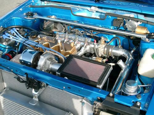
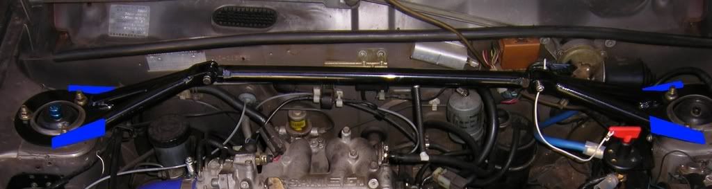
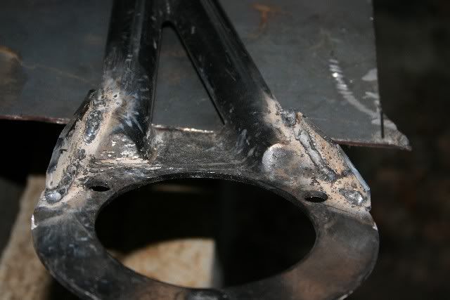
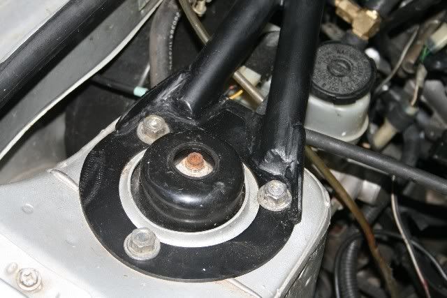
With the raised design needed to clear the intake gear you develop bending loads within the brace. The bending loads act on the least stiff part and the pin joints to the adjuster brace reduce the stiffness further because pin joints can’t pass a bending load that acts around their axis, and allows it to act as a mechanism. In this strut brace I found the weakest point then bends at the feet of the brace where it joins the strut tower, about the line shown below.
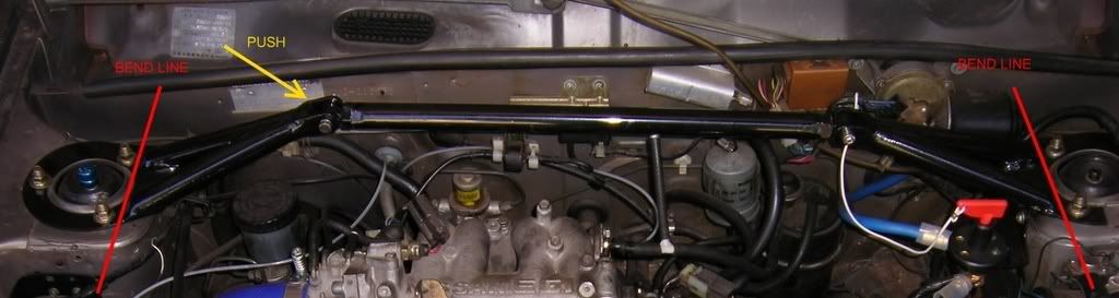
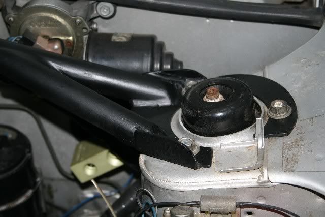
If you want to simulate what I’m talking about push on the elbow in the brace where the arrows are in the picture above.
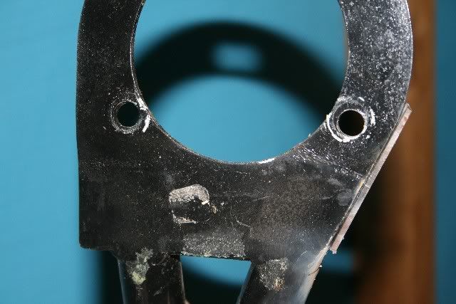
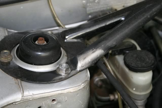
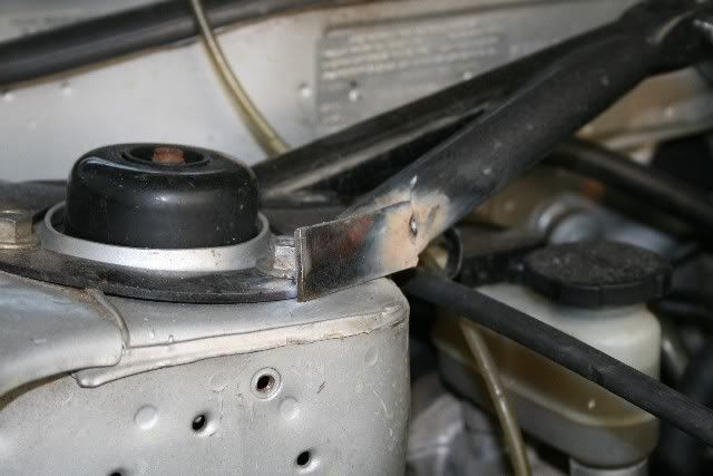
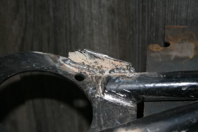
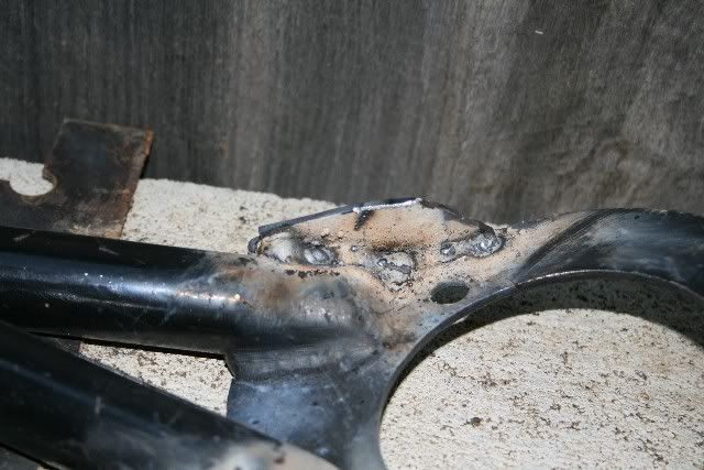
In these next images you can see the result of the bend:
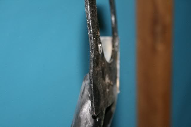
And the bend lines in the paint:
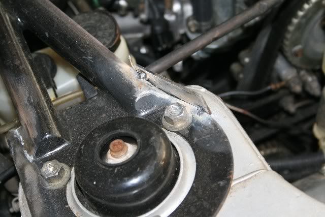
To improve this we just need to carry bending resistance out past the bolts by adding some simple vertical flanges.
So first I installed the brace and made sure it sat level and how I wanted it. This way it’ll be clamped while I tack weld it and be right after I take it off and complete the welds. Then I cleaned up the paint.
Tack welded some flanges:
Took the brace off and then filled the rest of the welds and flanges:
Before cleaning it up, painting it and putting it back on:
(I know my welding ain’t as good as Brendan’s)
The only other tip is to do with getting the adjustable brace tight enough. Make sure the install is tight and that the bolts won’t come out (before the nuts go on). This is done by making sure the bolts can’t be installed in the static position without a little bit of press to move the legs. This way the brace is preloaded and will have no slop.
Happy tuning!
And thanks again the Brendan for a good pair of Strut Braces!
C
For the rear, mine was a 'to the floor' option. The floor panel there is very thin and so moves easily. Using a larger footing plate or using more bolts spaced out would add significantly to the stiffness without adding much to the weight. Alternately, and this is what I did so as not to mod the brace, was add a large backing plate under the floor plan to increase the clamp area.
I found the front the braces are not that stiff once installed. This is because of a very simple to remedy.
When the strut towers move in under load they compress the brace. If the brace goes straight from one tower to the other there is no bending loads (as on the MRD brace), just compression.
With the raised design needed to clear the intake gear you develop bending loads within the brace. The bending loads act on the least stiff part and the pin joints to the adjuster brace reduce the stiffness further because pin joints can’t pass a bending load that acts around their axis, and allows it to act as a mechanism. In this strut brace I found the weakest point then bends at the feet of the brace where it joins the strut tower, about the line shown below.
If you want to simulate what I’m talking about push on the elbow in the brace where the arrows are in the picture above.
In these next images you can see the result of the bend:
And the bend lines in the paint:
To improve this we just need to carry bending resistance out past the bolts by adding some simple vertical flanges.
So first I installed the brace and made sure it sat level and how I wanted it. This way it’ll be clamped while I tack weld it and be right after I take it off and complete the welds. Then I cleaned up the paint.
Tack welded some flanges:
Took the brace off and then filled the rest of the welds and flanges:
Before cleaning it up, painting it and putting it back on:
(I know my welding ain’t as good as Brendan’s)
The only other tip is to do with getting the adjustable brace tight enough. Make sure the install is tight and that the bolts won’t come out (before the nuts go on). This is done by making sure the bolts can’t be installed in the static position without a little bit of press to move the legs. This way the brace is preloaded and will have no slop.
Happy tuning!
And thanks again the Brendan for a good pair of Strut Braces!
C