Hi Guys, looking at the egi manifold that im going to be installing it the following weeks it appears that the valves for the speed idle compensators are blocked off. Just wondering if this is an issue or is the compensator superfluous?
Cheers,
Reuben.
N12Turbo.com lanyards are now available! Click here to visit the shop
egi manifold installation
-
rubixcube101
- Posts: 94
- Joined: Wed Jun 13, 2012 12:31 pm
- Location: Perth
-
tassuperkart
- Administrator

- Posts: 5578
- Joined: Wed Jul 05, 2006 8:39 pm
- Location: Southern Tasmania
- Contact:
-
tassuperkart
- Administrator
- Posts: 5578
- Joined: Wed Jul 05, 2006 8:39 pm
- Location: Southern Tasmania
- Contact:
Ahh. Ok, EGI plenums dont have those valves the stock logs do apart from the AAIV on the end of the plenum
.
Connect switched 12v to that black housing on the end. Its identical in operation to the one on the stock log.
The other idle compensation valves live on the stock EGI throttle body.
E
.
Connect switched 12v to that black housing on the end. Its identical in operation to the one on the stock log.
The other idle compensation valves live on the stock EGI throttle body.
E
Forcd4 wrote:Oh fuk no dude it's you a again, the oracle.
-
rubixcube101
- Posts: 94
- Joined: Wed Jun 13, 2012 12:31 pm
- Location: Perth
-
rubixcube101
- Posts: 94
- Joined: Wed Jun 13, 2012 12:31 pm
- Location: Perth
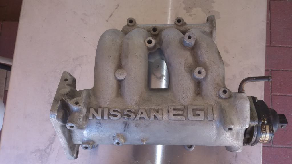
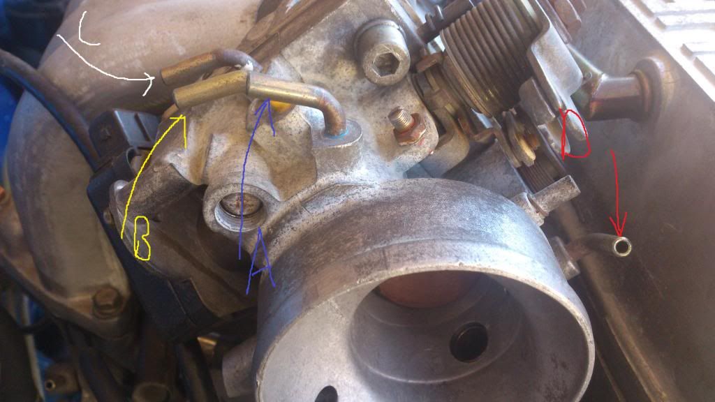
Hi, after searching through the forums page i still have no idea how to hook this thing up, especially the throttle body, so If someone could help that would be great! Doesn't make it any easier when everyone has different setups and i don't quite understand how all these vacuum lines work... thats the first problem. Ive taken some pictures and labelled the hoses that im uncertain about.
Second problem is that the original manifold that came with he manifold has had the injector holes welded up and thus is unusable. The stock manifold however has larger non-tapped holes, to large to put an m6 helicoil from what ive gathered. So i decided to get some larger bolts and put a nut on the end but that works for all but one which would require a 200mm bolt. Can i just leave this bolt out and hope that some sealant holds the manifold down tight?? Or is there another easy solution to this?
Behold the images:
Please correct me if im wrong. If theres any i've missed please let me know.
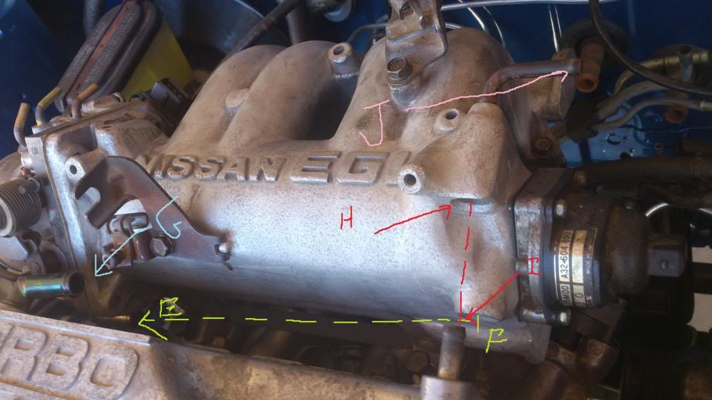
E and F go together and is the recirc line for the cold idle compensated.
Line G is a breather and goes back before the turbo but after the afm.
I believe the breather I is blocked off!! Does that make line H and J unuasable and is that an issue? I do have a spare rocker cover without any blocks, however this one is clean.
Thanks,
Reuben
Second problem is that the original manifold that came with he manifold has had the injector holes welded up and thus is unusable. The stock manifold however has larger non-tapped holes, to large to put an m6 helicoil from what ive gathered. So i decided to get some larger bolts and put a nut on the end but that works for all but one which would require a 200mm bolt. Can i just leave this bolt out and hope that some sealant holds the manifold down tight?? Or is there another easy solution to this?
Behold the images:
Please correct me if im wrong. If theres any i've missed please let me know.
E and F go together and is the recirc line for the cold idle compensated.
Line G is a breather and goes back before the turbo but after the afm.
I believe the breather I is blocked off!! Does that make line H and J unuasable and is that an issue? I do have a spare rocker cover without any blocks, however this one is clean.
Thanks,
Reuben
-
rubixcube101
- Posts: 94
- Joined: Wed Jun 13, 2012 12:31 pm
- Location: Perth
-
rubixcube101
- Posts: 94
- Joined: Wed Jun 13, 2012 12:31 pm
- Location: Perth
-
tassuperkart
- Administrator
- Posts: 5578
- Joined: Wed Jul 05, 2006 8:39 pm
- Location: Southern Tasmania
- Contact:
OK
You dont actually need any of them.
I simply bunged off all the sundry small rubber lines by first, grabbing the little pipes with a pair of pliers and winding them out. they are only lightly pressed in.
Then I tapped the holesm with an M4 or M6 taper tap, winding in some short bolts until they jammed hard in and then just ground off the screw heads with an angle grinder nice and neat.
You could even just wind in some self tappers nice and tight and grind off as above.
Now, you can hope all you like about leaving that long bolt out and you already know what the outcome will be.
Bodge something up like that and it will fail which is why you asked.
Just go down to your local nut and bolt shop and buy a length of M6 "Booker" rod, a Nylock nut and a single Wizznut (aka Flangenut)
Cut the booker rod to the length you need. Dont forget to leave enough rod each end for the nuts.
Wind on the Nylock a few threads. Now you have a long bolt dont you!!!!!!!!
Pass the bolt up from underneath and put the Wizznut on top...Voila!
I am good arent I!!!!!!!!!
Next is the idle bypass hose from the bottom of the TB to the hosetail on the right hand end of the Rocker cover. This provides a supply of air for the IAC on the TB. You need that to make the idle compensator valve work. Otherwise just block it off.
I connect that valve (single wire) at the back of the TB directly to the headlight low beam and adjust for a slight idle up when the lights come on.
In addition, you could use some diodes and connect up a wire from the rad fan and the interior fas as well to compensate for the heavy load and idle drop you get from these.
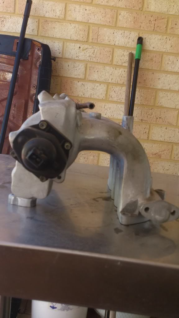
That last hole, angled forwards/down off the end of the plenum on the passengers side is for the PCV valve and that will cause you a lot of trouble without the entire setup from the EGI engine.
I made a bung and blocked that off entirely.
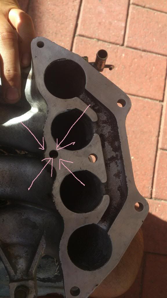
Now, see where the EGR valve usually lives on the end of the runners on the passenger side?
Heres mine. Youll see what I mean except I have tee'd in the idle solenoid valve on mine temporarily. Does confuse the image a bit.

Run a drill thru that and open it up. 8mm or so.
Make a small plate out of 6mm mild to bolt over that fitting.
Drill, tap ans screw in a brass hosetail or weld on a hosetail on, same size as the PCV valve hosetail.
Ask me real nice and I might make one for you for a six pack if you cant
Now connect the hosetail on the runners, via the PCV valve, to the hosetail on the rockercover! Make sure the PCV is around the right way so it can only allow air to pass INTO the manifold runners.
Voila again. Working PCV system, No stupid catch cans popped up dipsticks and leaking oil. All nice and neat and easy to remove rocker cover.
Lastly, thank me and tell me how good I am!!!!
Oracle
You dont actually need any of them.
I simply bunged off all the sundry small rubber lines by first, grabbing the little pipes with a pair of pliers and winding them out. they are only lightly pressed in.
Then I tapped the holesm with an M4 or M6 taper tap, winding in some short bolts until they jammed hard in and then just ground off the screw heads with an angle grinder nice and neat.
You could even just wind in some self tappers nice and tight and grind off as above.
Now, you can hope all you like about leaving that long bolt out and you already know what the outcome will be.
Bodge something up like that and it will fail which is why you asked.
Just go down to your local nut and bolt shop and buy a length of M6 "Booker" rod, a Nylock nut and a single Wizznut (aka Flangenut)
Cut the booker rod to the length you need. Dont forget to leave enough rod each end for the nuts.
Wind on the Nylock a few threads. Now you have a long bolt dont you!!!!!!!!
Pass the bolt up from underneath and put the Wizznut on top...Voila!
I am good arent I!!!!!!!!!
Next is the idle bypass hose from the bottom of the TB to the hosetail on the right hand end of the Rocker cover. This provides a supply of air for the IAC on the TB. You need that to make the idle compensator valve work. Otherwise just block it off.
I connect that valve (single wire) at the back of the TB directly to the headlight low beam and adjust for a slight idle up when the lights come on.
In addition, you could use some diodes and connect up a wire from the rad fan and the interior fas as well to compensate for the heavy load and idle drop you get from these.
That last hole, angled forwards/down off the end of the plenum on the passengers side is for the PCV valve and that will cause you a lot of trouble without the entire setup from the EGI engine.
I made a bung and blocked that off entirely.
Now, see where the EGR valve usually lives on the end of the runners on the passenger side?
Heres mine. Youll see what I mean except I have tee'd in the idle solenoid valve on mine temporarily. Does confuse the image a bit.
Run a drill thru that and open it up. 8mm or so.
Make a small plate out of 6mm mild to bolt over that fitting.
Drill, tap ans screw in a brass hosetail or weld on a hosetail on, same size as the PCV valve hosetail.
Ask me real nice and I might make one for you for a six pack if you cant
Now connect the hosetail on the runners, via the PCV valve, to the hosetail on the rockercover! Make sure the PCV is around the right way so it can only allow air to pass INTO the manifold runners.
Voila again. Working PCV system, No stupid catch cans popped up dipsticks and leaking oil. All nice and neat and easy to remove rocker cover.
Lastly, thank me and tell me how good I am!!!!
Oracle
Forcd4 wrote:Oh fuk no dude it's you a again, the oracle.
-
rubixcube101
- Posts: 94
- Joined: Wed Jun 13, 2012 12:31 pm
- Location: Perth
Haha you are good E! All makes sense, Thanks for all your help... i think we all agree this forum wouldn't be half as good/knowledgeable without you here.
Having a look i do have the fittings to use the hole for the pcv valve and the one below it. If i wanted to temporarily use the pcv hole and make my life difficult when it comes time to taking the rocker cover off, what goes on the 90deg hosetail sticking out on the otherside of the plenum? Does that go to your FPR?
Also whats the best way to make a tight seal on these bits when fitting them on the plenum?
Will definitely look to tapping into the egr runner when i get the chance, just need time to face it, drill it, tap it and make up the bracket. Think its a fantastic idea. University started so time is of the essence...
Thanks again for your help E, Legend.
Worked out how to resize my images
-
tassuperkart
- Administrator
- Posts: 5578
- Joined: Wed Jul 05, 2006 8:39 pm
- Location: Southern Tasmania
- Contact:
yep, the 90deg fitting is what i use for FPR. You can see it in my pix.
What bits do you mean "make a tight seal"????
The EGR port is already there and redy to go. You just have to drill it. ther bolt holes are there and tapped. Other than that you just have to make that small plate to bolt into position.
Cheers
Oracle
What bits do you mean "make a tight seal"????
The EGR port is already there and redy to go. You just have to drill it. ther bolt holes are there and tapped. Other than that you just have to make that small plate to bolt into position.
Cheers
Oracle
Forcd4 wrote:Oh fuk no dude it's you a again, the oracle.
-
rubixcube101
- Posts: 94
- Joined: Wed Jun 13, 2012 12:31 pm
- Location: Perth
Alright im back to finishing this project of 
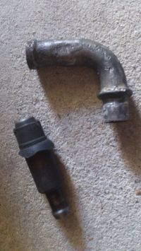
When i was referring to making a tight seal is im having a problem with the sleeved fitting. It just slips out far to easily and isn't tight enough. What can i use/do to hold it in there or seal around it when its fitted so it doesnt fall straight out and create vacuum leaks?
Thanks,
Reuben.
When i was referring to making a tight seal is im having a problem with the sleeved fitting. It just slips out far to easily and isn't tight enough. What can i use/do to hold it in there or seal around it when its fitted so it doesnt fall straight out and create vacuum leaks?
Thanks,
Reuben.
-
tassuperkart
- Administrator
- Posts: 5578
- Joined: Wed Jul 05, 2006 8:39 pm
- Location: Southern Tasmania
- Contact:
Initially, i used the PCV valve in the origial position on the EGI manifold.
I cant exactly remember what i did with it but i fitted some rubber tubing over the PCV valve to "shim" it up to make a seal inside the housing on the manifold and smeared on some Silastic to seal it up whick makes a mess and has to be cleaned off and redone EVERY time the rocker cover comes off..
It was a pita to fit the rocker cover and get a decent seal so i recommend you piss it off from there and move the pcv takeoff point to where i have shown in in the pix where the EGO valve sits.
Here:

Thats how I did it originally. Long gone now in favour of reloacating it to the runners as mentioned before.
Like this:

have fun.
Oracle
I cant exactly remember what i did with it but i fitted some rubber tubing over the PCV valve to "shim" it up to make a seal inside the housing on the manifold and smeared on some Silastic to seal it up whick makes a mess and has to be cleaned off and redone EVERY time the rocker cover comes off..
It was a pita to fit the rocker cover and get a decent seal so i recommend you piss it off from there and move the pcv takeoff point to where i have shown in in the pix where the EGO valve sits.
Here:
Thats how I did it originally. Long gone now in favour of reloacating it to the runners as mentioned before.
Like this:
have fun.
Oracle
Forcd4 wrote:Oh fuk no dude it's you a again, the oracle.
-
rubixcube101
- Posts: 94
- Joined: Wed Jun 13, 2012 12:31 pm
- Location: Perth